How to export gerber files from Altium Designer
It is not recommended to provide the PCB file (.pcbDoc file) to PCB manufacturer for production, because the manufacturer may not have the same version of Altium Designer as yours, and they may have different convention of handling each layer. Providing the PCB file directly may lead to misunderstanding and they may produce the PCB in a way that you don’t expect to.
The correct way is to export the PCB design to gerber files, which is a standard format for the industry and can avoid any misunderstanding. Each layer in your PCB design will have its own gerber files. You can zip all gerber files together and get a ZIP file that can upload to our inquiry form and get the PCB preview and also the estimated price. In this tutorial you will learn how to export your PCB design in Altium Designer to gerber files.
1. Set the Origin
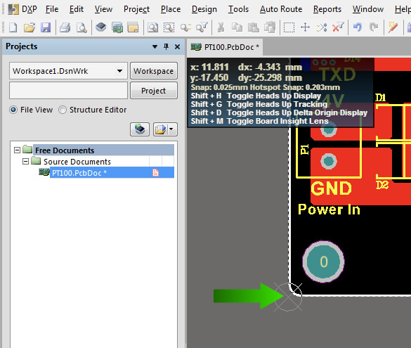
The first step is to set the origin point. You can do so by choosing menu Edit->Origin->Set.
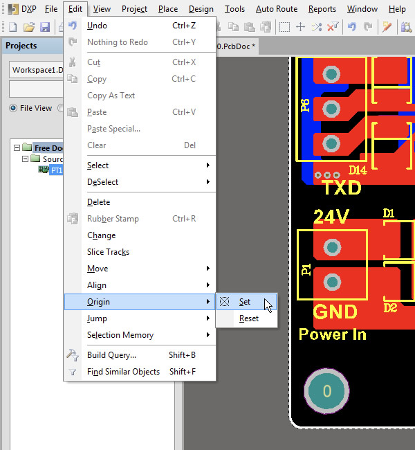
Set the left-bottom corner as the origin point.
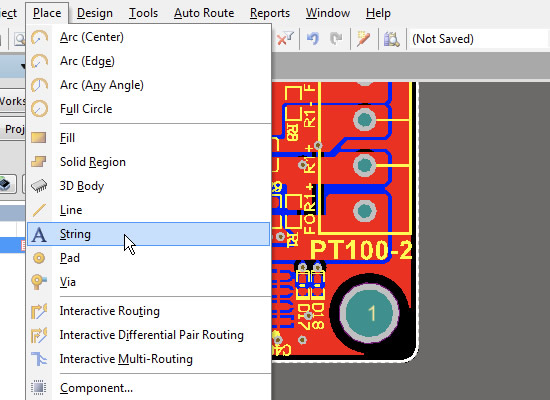
2. Place the .legend Text String
Place a text string on the right bottom corner of the board. You can do so by choosing menu Place->String.
Set the string text to “.Legend” and place it in layer Drill Drawing. You can choose the text height and style you like.
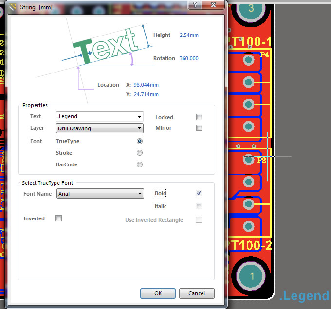
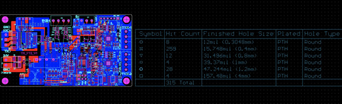
The .Legend is a special text string, which will be replaced by a table that contains information about the drilling holes on the board. You can see this table on the CAM preview after the gerber files are generated.
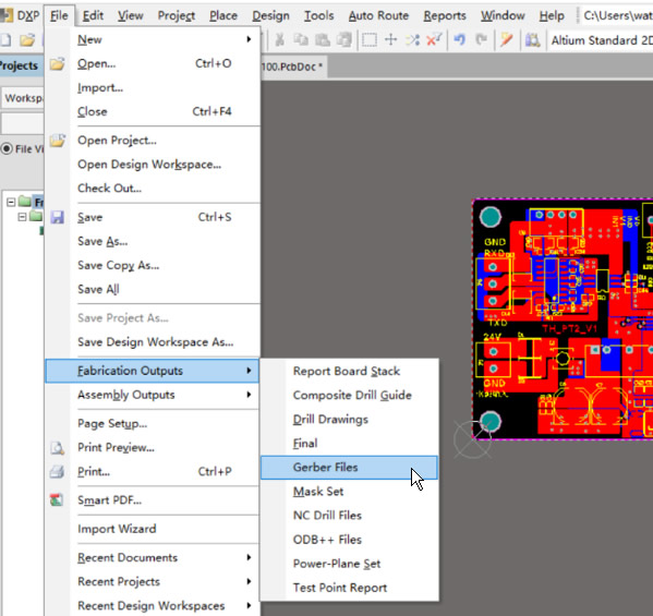
3. Output the Gerber Files
Now you can output the gerber files. Choose menu File->Fabrication Outputs->Gerber Files.
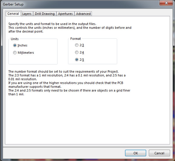
Then you will see the window for Gerber Setup. In the “General” tab you can choose the Units system. Either Inches or Millimeters will do, because the exported file will have the unit information and the manufacturer will not be confused. If you upload your gerber files (as a ZIP archive), the units will also be detected automatically.
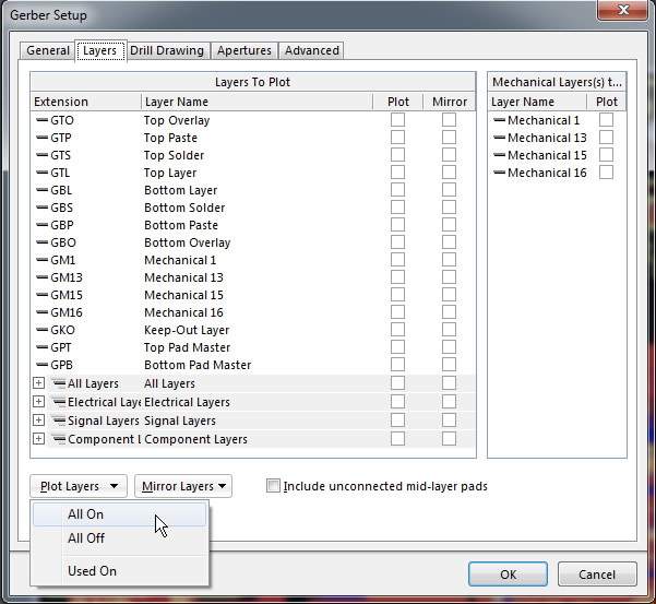
In the “Layers” tab you can choose which layers will be output. If you are not sure which layers are needed, just choose all of them by clicking the button Plot Layers->All On. The manufacturer will pick the required layers for production. All layers should not be mirrored, and you don’t need to add Mechanical Layers to all plots.
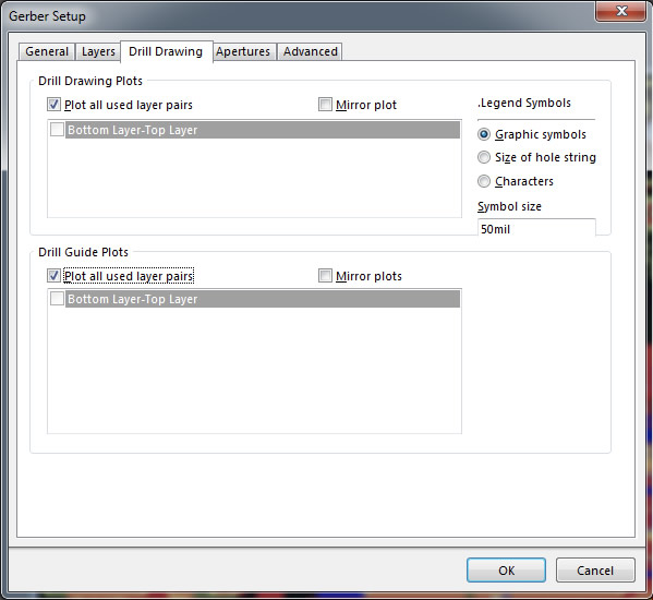
In the “Drill Drawing” tab you can put the drill drawing and drill guide information into the top and bottom layers. Here you can also choose the .Legend symbol (we found the graphic symbols look good).
As for the “Apertures” and “Advanced”, you can use default settings there and directly click the “OK” button to output gerber files. Altium Designer will create and open a file named “CAMtastic1.Cam”, which will show all the gerber drawings overlapped and also the drill hole information table (replaced the .Legend text string).
4. Output the NC Drill File
Besides the gerber files, you also need to export the NC drill File, so the manufacturer will know where and how to drill all those holes. In Altium Designer, which back to the PCB file and then go to menu File->Fabrication Outputs->NC Drill Files. Here you can use default values for all settings.
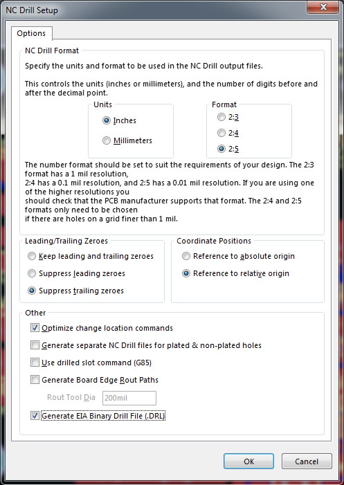
After clicking the “OK” button, it will ask for some information about units and tools. Here you can also use default values.
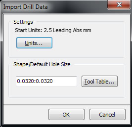 After clicking “OK” button again, the files are generated.